Simplifying Signal Access with Connectors

If you work directly with a Meadow F7 Feather or a Meadow Core Compute Module, accessing the hardware signals from your application is pretty simple and straightforward. The Meadow.Core stack exposes the Device.Pins collection so creating something as simple as an IDigitalOutputPort is pretty intuitive. You can look at the silkscreen for the pin you want, for example D00 and just use that in your code:
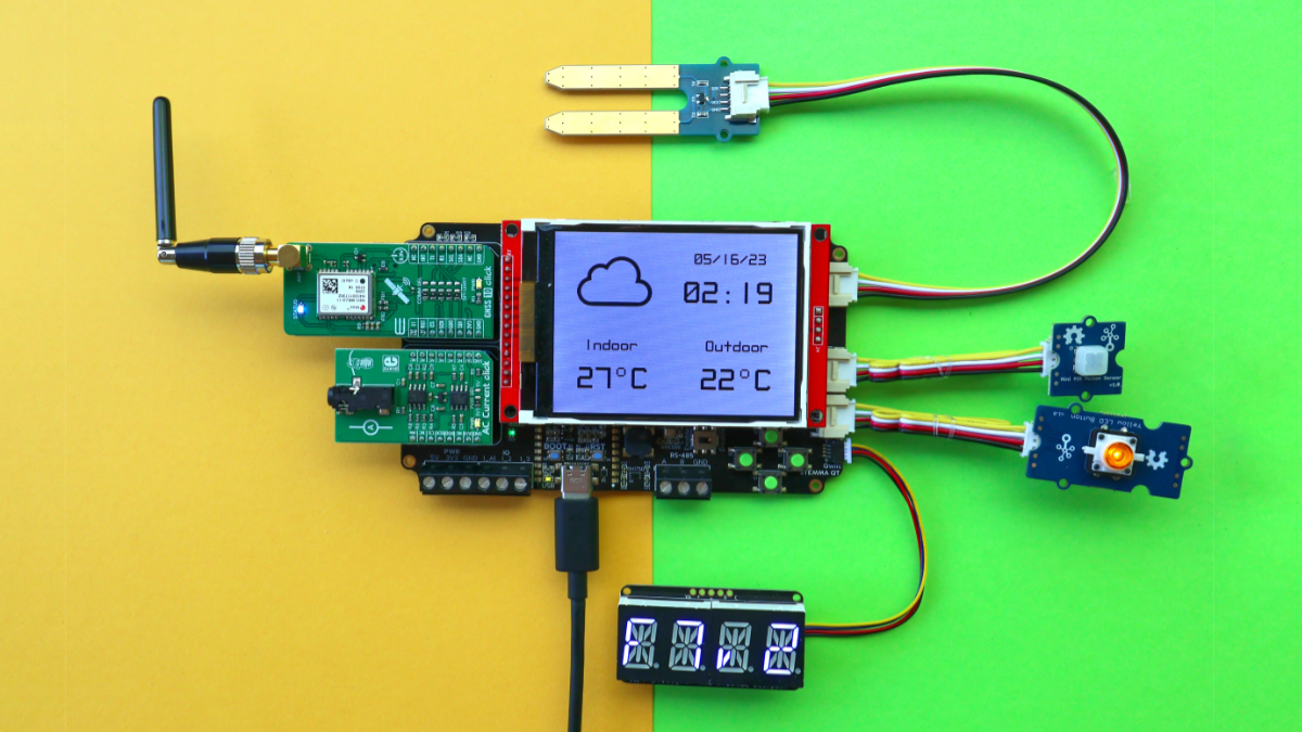
var output = Device.Pins.D00.CreateDigitalOutputPort();As the hardware grows in complexity, however, it becomes harder to keep things as straightforward. Take a look at the latest ProjectLab board (v3.e). It has connectors for standard hardware layouts like MikroBus, Grove and STEMMA. What if I want to control the signal that goes to, for example, the PWM pin on MikroBus Connector 1? There’s no obvious access to that pin in the Device.Pins collection, so you have to crack open the schematic to find that it’s routed to PB8 and your code would becomes:
// maps to the PWM pin on MicroBus 1 of ProjLab 3.e
var output = projLab.Pins.PB8.CreateDigitalOutputPort();
That code is definitely less readable. Without the comment line it’s not at all obvious what connector and pin on the hardware that would route to. To make matters worse, those pins has moved around across versions, so if you’re team is prototyping using multiple hardware revisions you then have to add check logic for the revision.
IDigitalOutputPort output;
// maps to the PWM pin on MicroBus 1 of ProjLab 1.x
if(projLab.RevisionString.StartsWith("1"))
{
    output = projLab.Pins.D04.CreateDigitalOutputPort();
}
else // maps to the PWM pin on MicroBus 1 of ProjLab 2+
{
    output = projLab.Pins.PB8.CreateDigitalOutputPort();
}
It gets even worse if the pin is connected to an I/O Extender like the MCP23008 used on version 2 and later. Now the pin might be in the Device.Pins collection, but it might be in the projLab.Mcp1.Pins collection instead, and again, that might shift with hardware revisions.
IDigitalOutputPort output;
if(projLab.RevisionString.StartsWith("1"))
{
    output = projLab.Pins.D03.CreateDigitalOutputPort();
}
else
{
    output = projLab.Mcp_2.Pins.GP3.CreateDigitalOutputPort();
}
So how do we resolve this mess and provide a coherent API that allows you to avoid the schematic lookup, provides hardware portability, and makes the code more readable? The answer is to use (and implement if you’re making your own board) the Connector pattern introduced in Meadow.Core version 1.2.
A Connector is essentially a collection of named IPins that also contains a signal mapping connecting the name to and underlying signal. This provides the ability to give a Connector Pin a name that matches the silkscreen. The Connector implementation itself can dynamically detect hardware revision and alter the mapping at startup, providing platform portability. And by simply adding a Connector to your board-level abstraction, the code becomes very readable.
For example, look at the samples below. You can tell exactly what they’re doing, they don’t require a schematic, and they work on all versions of the ProjectLab that we’ve made without any reviion check in the application.
var mb1_pwm = projLab.MikroBus1.Pins.PWM.CreatePwmPort();
var grove_input = projLab.GroveDigital.Pins.D1.CreateDigitalInputPort();
var stemma_output = projLab.QwiicConnector.Pins.Scl.CreateDigitalOutputPort();
var grove_analog = projLab.GroveAnalog.Pins.D0.CreateAnalogInputPort(1);
If you are already using a ProjectLab board or if you’re creating your own boards, give the new Connector API a try and let us know what you think over in our public Slack!


