

The Smartening of my Dehydrator – Part 2; Temperature Control
In part 1 of this blog series, we looked at the dehydrator system as a whole. In this post in the dehydrator hacking series, we’re going to explore how to control the fan and heater in the dehydrator using relays to regulate temperature. We’ll explore the practical use of the Proportional, Integral, Derivative (PID) algorithm to actually provide a control for the system to drive temperature, and the role that Pulse-Width-Modulation (PWM) plays in providing an intermediate power value in a control system that only has off and on.
Fan and Heater Element
Both the fan and the heater in my dehydrator run on AC electricity. However, the Netduino runs on low voltage DC electricity. These two electricity types do not mix well, so the fan and heater power is controlled via relays.
Relays
Relays are (usually) electromagnetic switches whereby the controlling circuit and the circuit being controlled are completely isolated. This allows you to control AC electricity with a small amount of DC current.
Relays have some interesting behaviors since they’re electromagnetic, and require a few supporting components, so for prototyping, we just just pre-built relay boards, like this Keyestudio 2 channel relay board:

Because of their power draw, these were probably the most complicated part of the whole process. USB nominally only supplies 400mA of power, however, each of these relays takes 120mA @ 5V. At first, I had them on the 5V power supply as the Netduino, but when they both turned on, strange things happened because they maxed out the power draw on the USB.
This had a couple of side effects. First, the reported temperature on the analog temperature sensor spiked, because the 3.3V power rail on the Netduino dropped down to around 3.0V, which meant that the Analog to Digital Converter (ADC) was comparing the analog voltage to 3.0V, instead of 3.3V, making it seem like the voltage reading was higher than it actually was.
Second, sometimes, when the relays switched off, my LCD screen would display garbage, and the Netduino was reading button clicks from the rotary encoder button. Both of these were due to a power spike hitting the Netduino when the magnetic field collapsed in the relay coil. The following image from my oscilloscope shows the spike occurring:
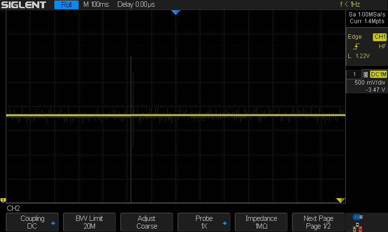
It’s a little hard to see, but it’s the yellow vertical line in the first third of the image.
Relay Power Solution
I fixed the analog voltage readings by supplying the relay with its own power from a second USB. This removed the power draw from the Netduino and therefore, it could keep a steady 3.3V to the temperature sensor. However, I still had the power spike issue when the relays switched off.
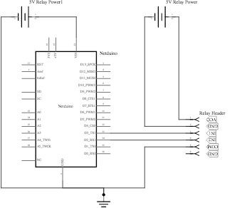
It turns out, the Keyestudio relay boards have an undocumented fix for this. They have an internal circuit that isolates their power rails from the inputs from the Netduino, but it requires you to remove the jumper on the header that connects COM and GND, and instead wire it up as follows:
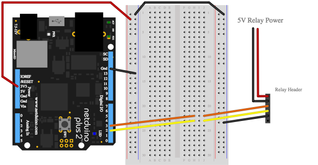
From a breadboard perspective, this circuit looks like the following:
Best Practice: Don’t Spin your Wheels
This power problem brings up a best practice when working with hardware: don’t spin your wheels. I didn’t solve this power isolation issue for a while after I had been working on the dehydrator, and instead of just getting stuck on that one issue, I moved on to other tasks and revisited this issue later.
Temperature Control with PWM and PID
The temperature of the dehydrator is controlled by turning the heater element on and off in such a way that it maintains the temperature set by the user.
PWM
Cycling power between off and on like this is called Pulse-Width-Modulation (PWM). The percentage of time that the power is on, is called the duty cycle, and PWM is a way to provide an intermediate average value between on and off:
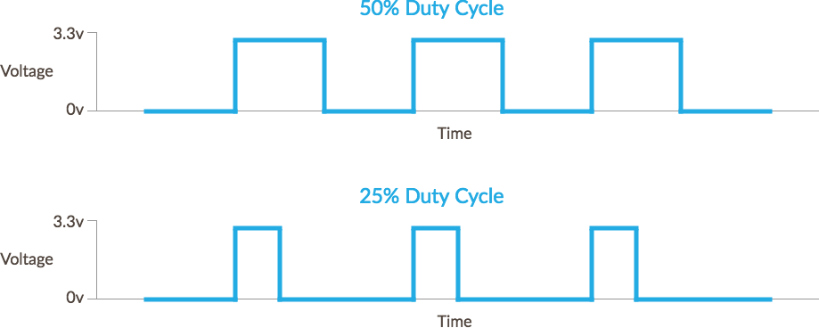
Most PWM signals involve rapid cycling, known as the frequency; usually many thousand times per second. However, because we’re using electromechanical relays that don’t switch that fast, and also have a finite lifetime of switching, we use a very slow PWM frequency. In fact, because of the thermal inertia of the system, we can get away with cycling the power to the heater in 30 second or longer intervals.
Netduino.Foundation SoftPWM Generator
Netduino has 6 PWM pins in which are hooked to an internal timer on the Netduino microcontroller so that PWM generation is done in hardware and doesn’t take processing time. However, the hardware PWM generator is only good for about 1hz or faster PWM, and setting the frequency to anything below that will cause an exception.
For this reason, I created Netduino.Foundation’s SoftPWM generator, which generates a PWM signal via code, and allows you to have very slow PWM signals.
PID
Using a PWM signal is useful in generating an intermediate heat output, but we need to calculate how much power is needed to get it to the target value, and keep it there, efficiently.
The simplest algorithm would be to turn on the heater, wait until it hit the correct temperature, turn it off, then repeat, but that wouldn’t be very efficient, as it would cause a lot of temperature oscillation:
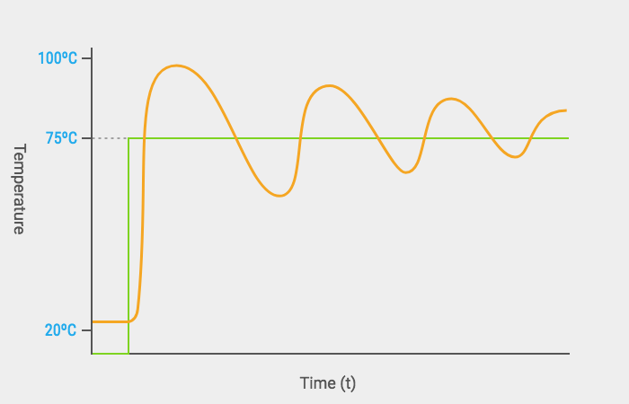
What we really want is something like:

Enter PID. PID stands for Proportional, Integral, Derivative, and it’s the quintessential industrial control algorithm. PID is used in cars to make cruise control work, in drones to attain level flight in changing conditions, and on ships to keep a steady heading while at sea. It’s also used in nearly every heating control system out there.
We wrote some fantastic documentation on PID, and Netduino.Foundation has built in PID controllers so you don’t have to implement the algorithm yourself. I highly recommend reading through the guides, but with Netduino.Foundation, you don’t have to understand the ins and outs to implement PID.
Control Theory
One key concept to understand when building hardware is the idea of controllers. They may be somewhat of a foreign concept to many software developers, but they’re very common in hardware development.
PID uses a closed loop gain controller, so-called because the control output is fed back into the system and the controller is then given the response to its previous control signal and can react appropriately to the change and further refine the output:
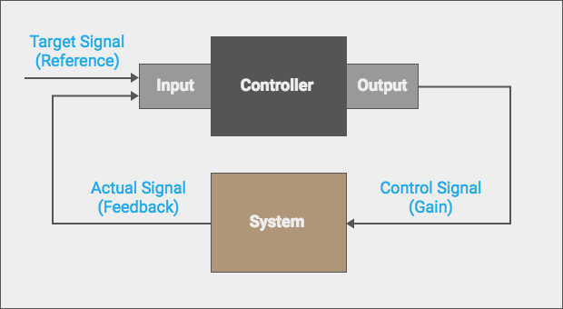
This concept of encapsulating functionality into some sort of logical container such as a class is not uncommon in programming, but in hardware, controllers are used everywhere, and these feedback loops are often an integral part of them. We’ll examine the use of controllers as a pattern when we look at the code that powers the dehydrator app.
PID Tuning
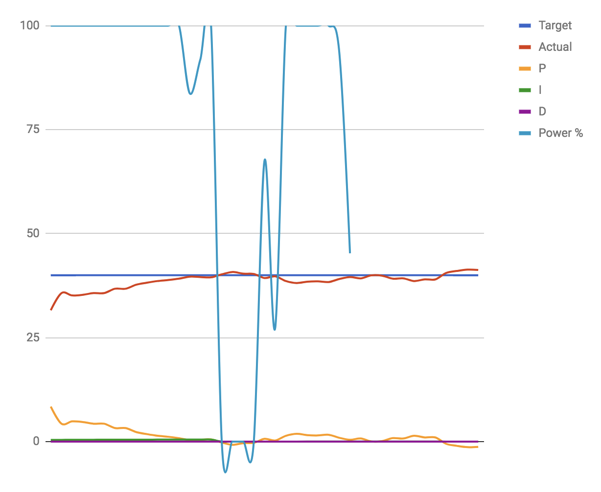
There are a lot of different ways to tune the control inputs to the PID algorithm; you can use some really fancy math and autotune with linear quadratic regulators and other calculus magic, or you can do what most people do, try some reasonable starting values, and see how the system reacts. In our case, we did just that and used a google spreadsheet to plug in the system values and graph the output:
One of the great features of the PID controllers in Netduino.Foundation, is that they have an tuning output. Simply set OutputTuningInformation to true, and they’ll output tuning information to the console, which can be pasted into a spreadsheet to visualize the system’s response.
We used a Google spreadsheet, and you can see our outcomes on it here. You can use this spreadsheet yourself, if you have a Google account. Choose File menu > Make a Copy. To use the spreadsheet, delete the existing data and then copy the tuning output from the console and past it into the first cell of the second row, then have Google Sheets automatically split it into columns. The graph should then show you the system response.
In our case, we only used the proportional (P) and integral (I) component gains of the PID controller, and we started by setting P = 1, and then once we had a good response curve with that alone, we set I = 1 and went from there. Generally, the P component will affect the amplitude of the wave, and the I component will affect the duration.
By taking this approach it only took us a handful of runs to get to a good system response, and ultimately, we were able to very easily create an application that has just as good, or better, temperature control than the other appliances in my house!
Next up, we’re going to take a look at the rest of the hardware and see how it all fits together, as well as how user input is captured, both from the LCD GUI system, and the web API. Stay tuned!