Hack Kit Series: Closer look at Push Buttons
Hello friends,
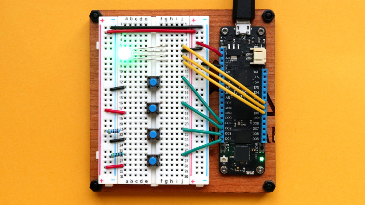
In this blog post I want to show you how we simplified the way to use push buttons on Meadow for beta 4.5 release (which is included in the Meadow Hack Kit) using Meadow.Foundation.
Important Note: whenever we’re working with Digital Interrupt Ports, lets check the Meadow F7 Micro pinout diagram below and pay close attention to the Interrupt Group on each pin.

When you plan to use Interrupt ports for things like push buttons, rotary encoders and such, be sure to only use one pin per Interrupt Group. For example, you wouldn’t be able to configure pins D14 and D15 as interrupt ports since both belong to the Interrupt Group 03. The app will throw an exception informing us that Interrupt Group 03 is being used more than once.
Also notice that you can even configure the Analog pins as Interrupt Ports for when you’re not using them in your project.
Circuit Sample
In the Fritzing diagram below, there is four different ways we can connect push buttons to Meadow:
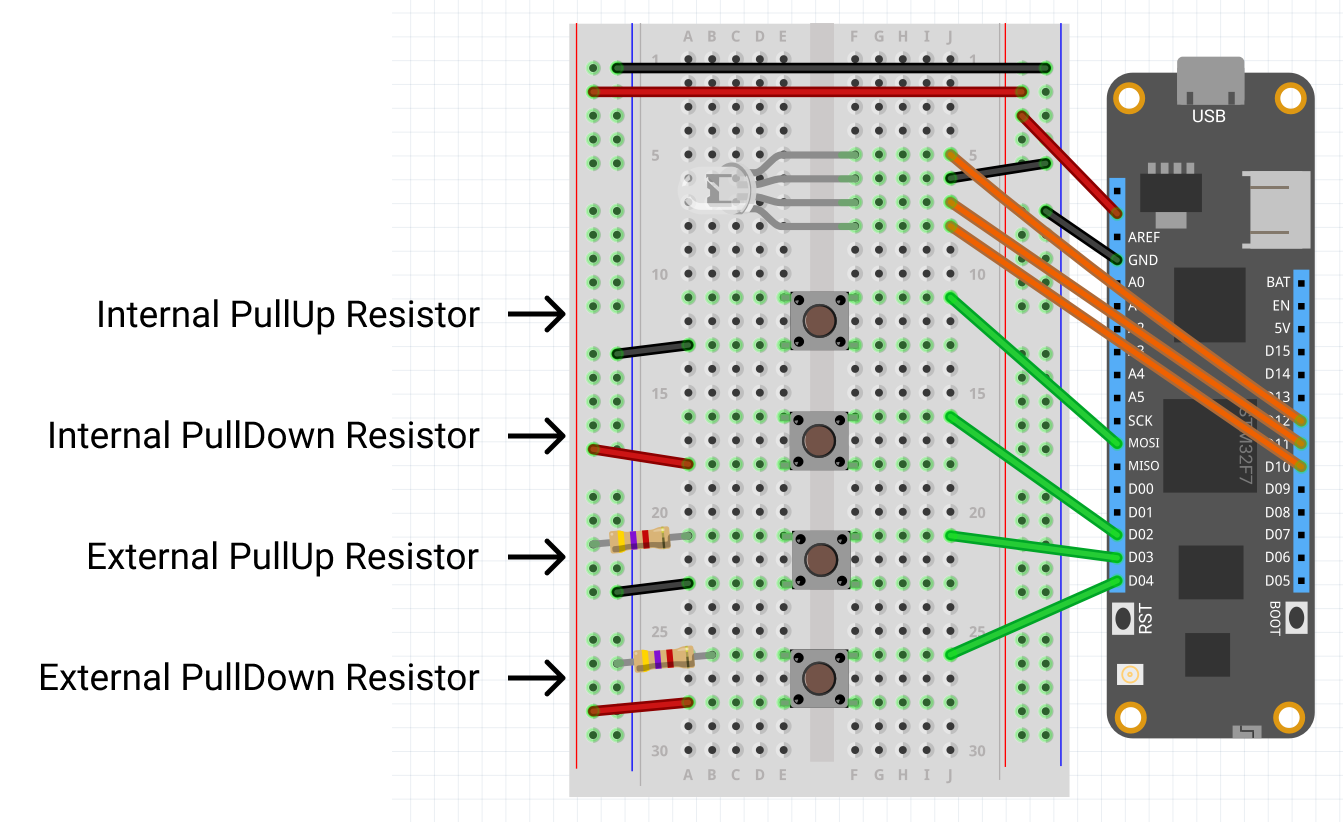
From the pinout shown above, we’re wiring four push buttons that belong to different Interrupt Groups:
- Pin MOSI belongs to Interrupt Group 05
- Pin D02 belongs to Interrupt Group 06
- Pin D03 belongs to Interrupt Group 08
- Pin D04 belongs to Interrupt Group 09
To get user feedback, we’re wiring a common-ground RGB LED connected to pins D10, D11 and D12, but you can use the Onboard RGB LED as well.
Code Sample
Consider the following code snippet that will work as a starting point before we start going through all the ways you can initialize the buttons. We’ll have a List of PushButton, and as we go through each case, we’ll add these button objects to the list, and finally we’ll iterate through all the PushButton items on the list to register the event handlers to each one.
public class MeadowApp : App<F7FeatherV2>;
{
    RgbPwmLed led;
    List<PushButton> pushButtons;

    public MeadowApp()
    {
        Console.WriteLine("Initializing...");

        led = new RgbPwmLed(
            Device.Pins.D12,
            Device.Pins.D11,
            Device.Pins.D10);
        led.SetColor(Color.Green);

        pushButtons = new List<PushButton>();

        // [TODO: PushButton Initializing logic here]

        foreach (var pushButton in pushButtons)
        {
            pushButton.Clicked += PushButtonClicked;
            pushButton.PressStarted += PushButtonPressStarted;
            pushButton.PressEnded += PushButtonPressEnded;
            pushButton.LongPressClicked += PushButtonLongPressClicked;
        }
    }

    void PushButtonClicked(object sender, EventArgs e)
    {
        led.SetColor(Color.Orange);
        Thread.Sleep(500);
        led.SetColor(Color.Green);
    }

    void PushButtonPressStarted(object sender, EventArgs e)
    {
        led.SetColor(Color.Red);
    }

    void PushButtonPressEnded(object sender, EventArgs e)
    {
        led.SetColor(Color.Green);
    }

    void PushButtonLongPressClicked(object sender, EventArgs e)
    {
        led.SetColor(Color.Blue);
        Thread.Sleep(500);
        led.SetColor(Color.Green);
    }
}
We have an RgbPwmLed named Led (which after initialized it will turn Green), and it will change colors depending on the events triggered:
- PushButtonClicked – The LED will turn Orange for 500ms before going back to Green.
- PushButtonPressStarted – The LED will turn Red to indicate the button is pressed and held down.
- PushButtonPressEnded – The LED will turn back to Green from being Red as it was held down.
- PushButtonLongPressClicked – The LED will turn Blue for 500ms before going back to Green.
Theres two ways you can create a PushButton object:
- Pass in the constructor the Device object and Pin the button is connected to along with the ResistorType to indicate how you have the Button wired up.
- Pass in the constructor a DigitalInputPort connected with the ResistorType to indicate how you have the Button wired up.
We will go through each option to wire up a PushButton and show both ways to instantiate an object. Be sure to only use one of the two ways to initialize a PushButton object to the pushButtons list.
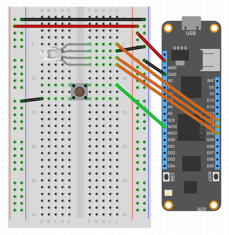
Option 1 – Using the internal pull up resistor
In this option, Meadow is capable of keeping the baseline input signal high, and so when the user presses the button, the pin connected to ground will bring the signal down, causing the interrupt to trigger events mentioned above. The internal pull up resistor is used to prevent a short circuit that could damage the board.
Circuit sample
Initialize with DigitalnputPort and ResistorMode.InternalPullUp
pushButtons.Add(new PushButton(Device.CreateDigitalInputPort(
    Device.Pins.MOSI, ResistorMode.InternalPullUp, 25, 50)));
Initialize with Device, Pin and ResistorMode.InternalPullUp
pushButtons.Add(new PushButton(Device, Device.Pins.MOSI,
    ResistorMode.InternalPullUp));
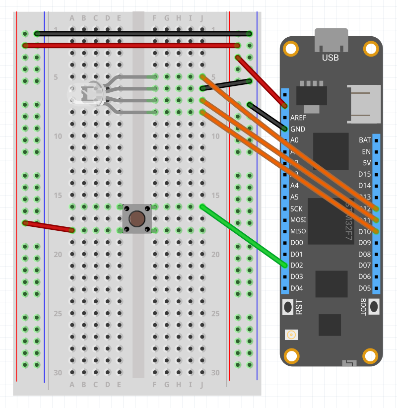
Option 2 – Using the internal pull down resistor
In this option, Meadow is capable of keeping the baseline input signal low, so when the user presses the button, the pin connected to VCC will bring the signal up, causing the interrupt to trigger events mentioned above. The internal pull down resistor is used to prevent a short circuit that could damage the board.
Circuit Sample
Initialize with DigitalnputPort and ResistorMode.InternalPullDown
pushButtons.Add(new PushButton(Device.CreateDigitalInputPort(
    Device.Pins.D02, ResistorMode.InternalPullDown, 25, 50)));
Initialize with Device, Pin and ResistorMode.InternalPullDown
pushButtons.Add(new PushButton(Device, Device.Pins.D02,
    ResistorMode.InternalPullDown));
Option 3 – Using an external pull up resistor
In this option, we are not using the internal pull up resistor, so we’re leaving the Input Port in a floating signal but we’re stablishing a base line using an external pull up resistor instead connected to VCC. When the button is pressed, the signal is now low and will trigger the events configured previously.
Circuit sample
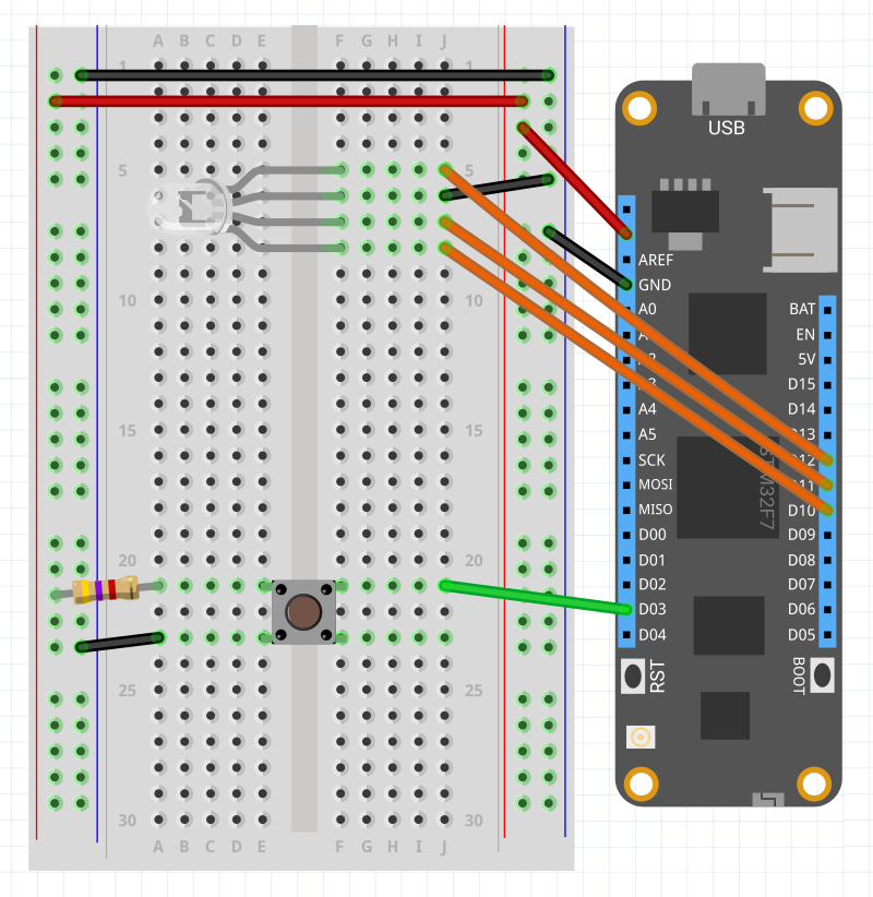
Initialize with DigitalnputPort and ResistorMode.ExternalPullUp
pushButtons.Add(new PushButton(Device.CreateDigitalInputPort(
    Device.Pins.D03, ResistorMode.ExternalPullUp, 25, 50)));
Initialize with Device, Pin and ResistorMode.ExternalPullUp
pushButtons.Add(new PushButton(Device, Device.Pins.D03,
    ResistorMode.ExternalPullUp));
Option 4 – Using an external pull down resistor
In this option, we are not using the internal pull down resistor, so we’re leaving the Input Port in a floating signal but we’re stablishing a base line using an external pull down resistor instead connected to VCC. When the button is pressed, the signal is now high and will trigger the events configured previously.
Circuit sample
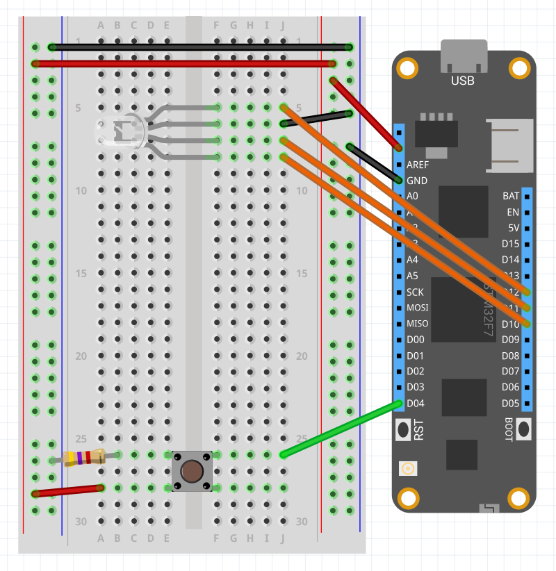
Initialize with DigitalnputPort and ResistorMode.ExternalPullDown
pushButtons.Add(new PushButton(Device.CreateDigitalInputPort(
    Device.Pins.D04, ResistorMode.ExternalPullDown, 25, 50)));
Initialize with Device, Pin and ResistorMode.ExternalPullDown
pushButtons.Add(new PushButton(Device, Device.Pins.D04,
    ResistorMode.ExternalPulldown));
That’s all I have for you today on this blog post on A Closer Look at series. Feel free to reach us on any of our social channels for any requests on other peripherals included in the Hack Kit.
Happy hacking,
Jorge


