Hack Kit Series: Closer look at 20×4 LCD character display
Hello friends,
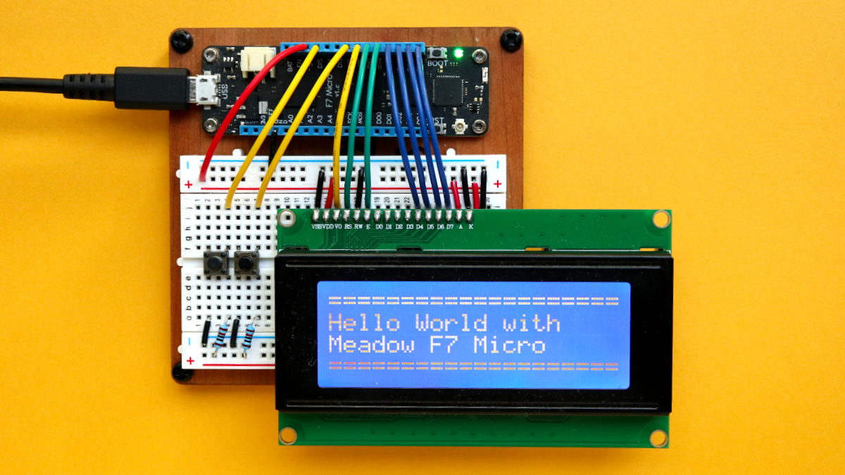
Just wanted to write a blog post about how incredibly easy is to wire up an LCD 20×4 character display (which is included in the Meadow Hack Kit) using Meadow.Foundation.
First thing you’ll need to do is search and install the Meadow.Foundation.Displays.LCD.CharacterDisplay NuGet package in your Meadow Application project.
After that, there’s three ways you can wire up and instantiate the CharacterDisplay on your project:
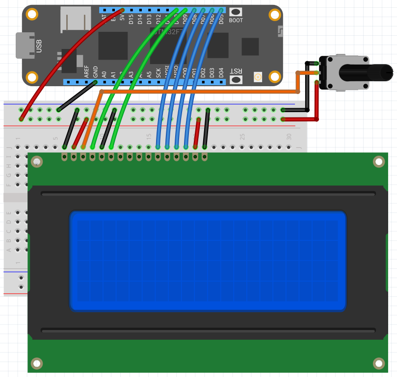
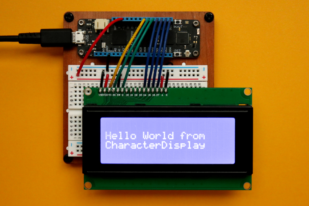
Option 1 – Digital IO with manual contrast control
Circuit sample
Code sample
var display = new CharacterDisplay
(
    pinRS: Device.Pins.D10,
    pinE: Device.Pins.D09,
    pinD4: Device.Pins.D08,
    pinD5: Device.Pins.D07,
    pinD6: Device.Pins.D06,
    pinD7: Device.Pins.D05,
    rows: 4, columns: 20
);

display.WriteLine("Hello World from", 1);
display.WriteLine("CharacterDisplay", 2);
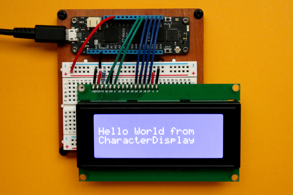
In this case, pass all the Meadow device pins to display’s constructor. You will need to use either a resistor or potentiometer on the contrast pin (V0) so you can adjust it manually. In the image below I used a 2.2K ohm resistor to get the contrast I want.
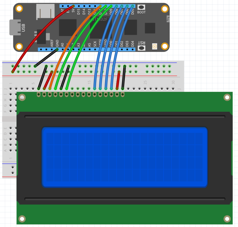
Option 2 – Digital IO with a PWM port connected to the contrast pin (V0)
Circuit diagram
Code sample
var display = new CharacterDisplay
(
    pinV0: Device.Pins.D11,
    pinRS: Device.Pins.D10,
    pinE:  Device.Pins.D09,
    pinD4: Device.Pins.D08,
    pinD5: Device.Pins.D07,
    pinD6: Device.Pins.D06,
    pinD7: Device.Pins.D05,
    rows: 4, columns: 20
);
In this option, you don’t need a specific resistor or potentiometer to adjust the contrast on your display. Simply pass in a PWM capable pin of your Meadow (D02 – D13), and the driver itself will set the contrast.
Option 3 – Using an I2C backpack interface
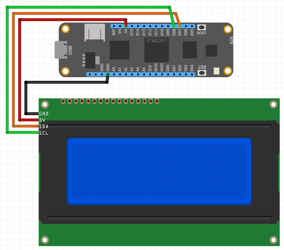
To use your display with this option, you’ll need to get a I2C interface module that it has to be soldered on the pins on the back of the display:

With this module, you no longer need to use up to seven digital pins off your Meadow board, but the two I2C capable pins instead, which at the same time you can connect more peripherals that also use the I2C bus.
Circuit sample
Code sample
var display = new CharacterDisplay
(
    i2cBus: Device.CreateI2cBus(I2cBusSpeed.Standard),
    address: I2cCharacterDisplay.DefaultI2cAddress,
    rows: 4, columns: 20
);

display.WriteLine("Hello World from", 1);
display.WriteLine("CharacterDisplay", 2);
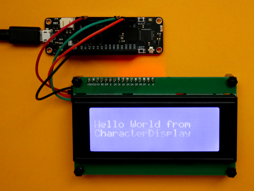
Instantiating the CharacterDisplay this way, notice you just need to pass the I2c bus, the address of the peripheral which is included already in the driver as a constant (normally the address is 0x27, but it ranges from 0x20 to 0x27). You can use a screwdriver to turn the blue potentiometer on the module to adjust the contrast:
That’s a wrap!
That’s all I wanted to show you on this post. Be sure to check the official API docs we have available for this awesome peripheral. Last thing I want to mention is you might want to go to Hackster to check these projects that use the CharacterDisplay:
- Christmas Countdown Timer w/ an LCD Display, RTC and Meadow
- Build a Clock with Meadow’s Onboard Real Time Clock Chip
Happy hacking!
Jorge


