Connected Coffee Maker Part 2 – Control
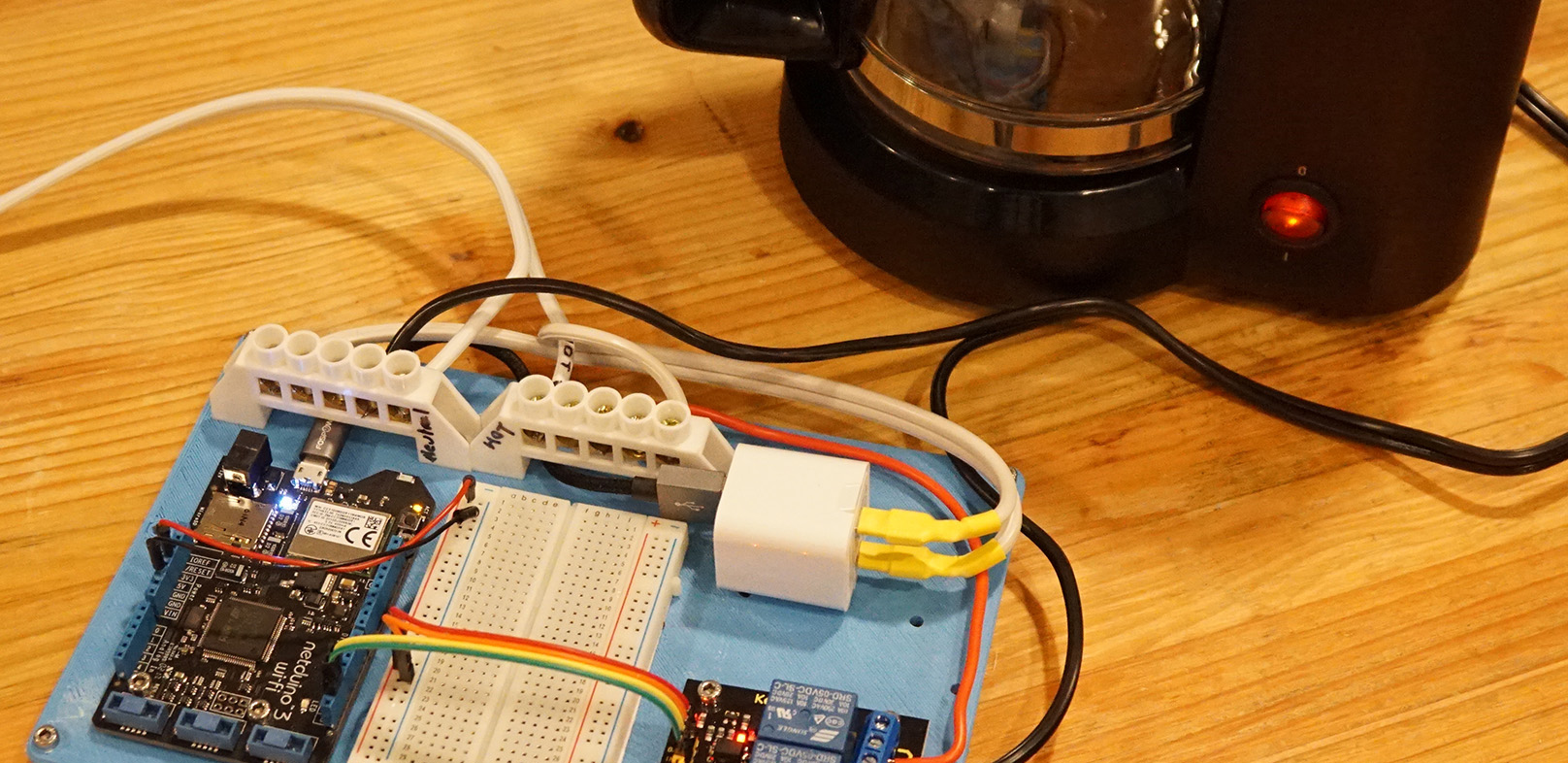
In part 1 of this series we created a power adapter from a USB charger that can be used to power a Netduino when it isn’t plugged into the computer. In this part, we’re going to create what is, in essence, a smart power outlet; a household electrical circuit that can be turned on or off by a Netduino. In this example, we’re going to use a simple coffee pot that has an on/off switch, but any simple appliance can be controlled this way. Later on, we’ll add more complexities such as controlling this outlet via a mobile app talking to a web API on the Netduino.
Materials Required
- Coffee maker with on/off switch (or any simple on/off appliance)
- USB power adapter from Part 1 (this is only needed when the Netduino isn’t plugged into a computer)
- 3D Printable Baseboard (this is just the 3D file, it needs to be printed)
- Screw terminal blocks
- Double-sided mounting tape
- Half size breadboard
- 12mm M3 socket screws
- M3 nuts
- Keyes 2 channel relay
- 16-18 gauge extension cord
- Male to female jumper wires
- Male to male jumper wires
Tools Required
- 3.2mm (1/8″) drill bit – for reaming out the holes on the board
- 2.5mm hex key (for M3 socket screws)
- Wire stripper
- Phillips head screwdriver
- Soldering iron + solder (optional, for prepping wire ends)
Warning
Before going any further, it’s important to note that this project is meant to control household electricity. That’s 120V in North America, and 240V in many other places. Household electricity can kill you. It probably won’t; I’ve done enough electrical household wiring to be shocked more times than I care to admit, but in certain situations, it certainly can be deadly. When this project is assembled and plugged in, the terminal blocks and relay terminals will be live and can shock you if not handled with care. All the live conducts are protected by plastic, but if you stick metal, such as a screwdriver in them, you can get shocked. Keep this prototype away from children who might stick small fingers into the terminals or get a hold of the live wires some other way. Additionally, when not in use, it should be unplugged from the electrical outlet.
Step 1 – Print Baseboard and Clean Holes
First, we need a baseboard to put all of our prototype boards on. Download and print the Appliance Control Board from our 3D print designs GitHub repo. If you don’t have a 3D printer, you can also make one of these from a 3/16″ – 1/4″ thick sheet of plywood. The 3D print repo contains the original .DWG file with dimensions. AutoDesk publishes viewers to view the file to get dimensions.
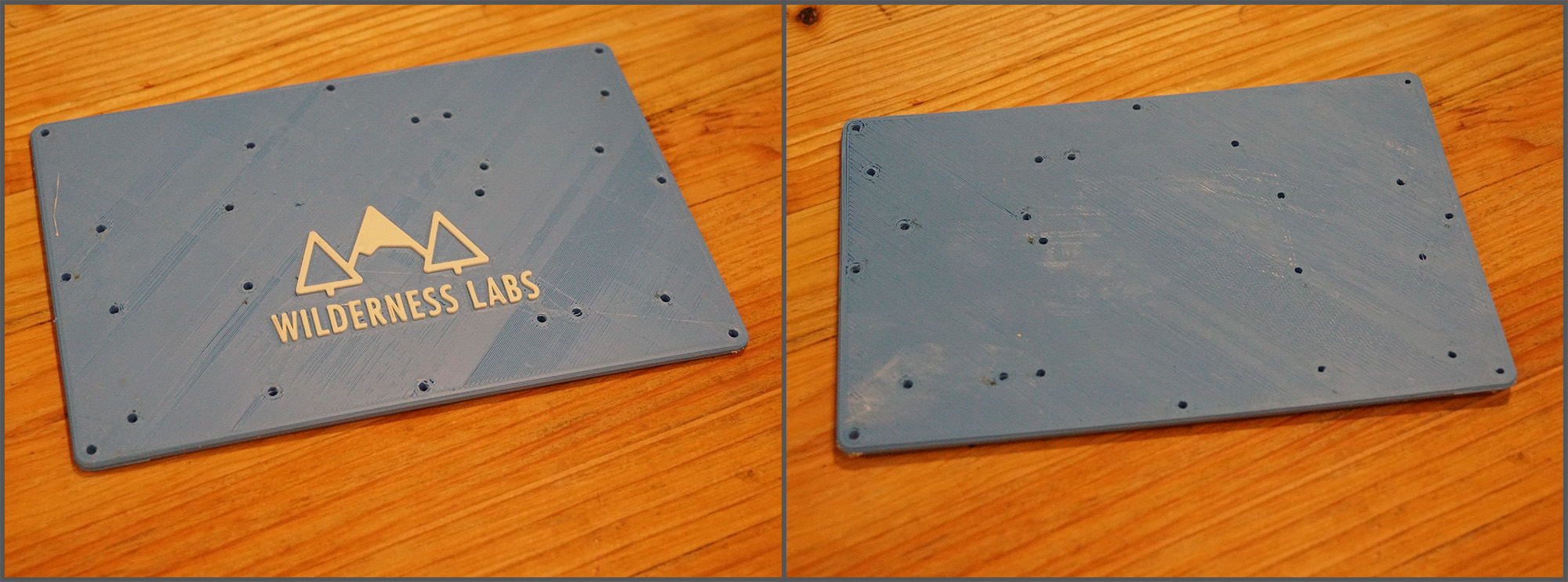
After it’s printed, I find that the holes usually need to be reamed out with a 3.2mm (1/8″) drill bit, otherwise the bolts don’t fit through.
Step 2 – Attach Screw Terminal Blocks and Boards
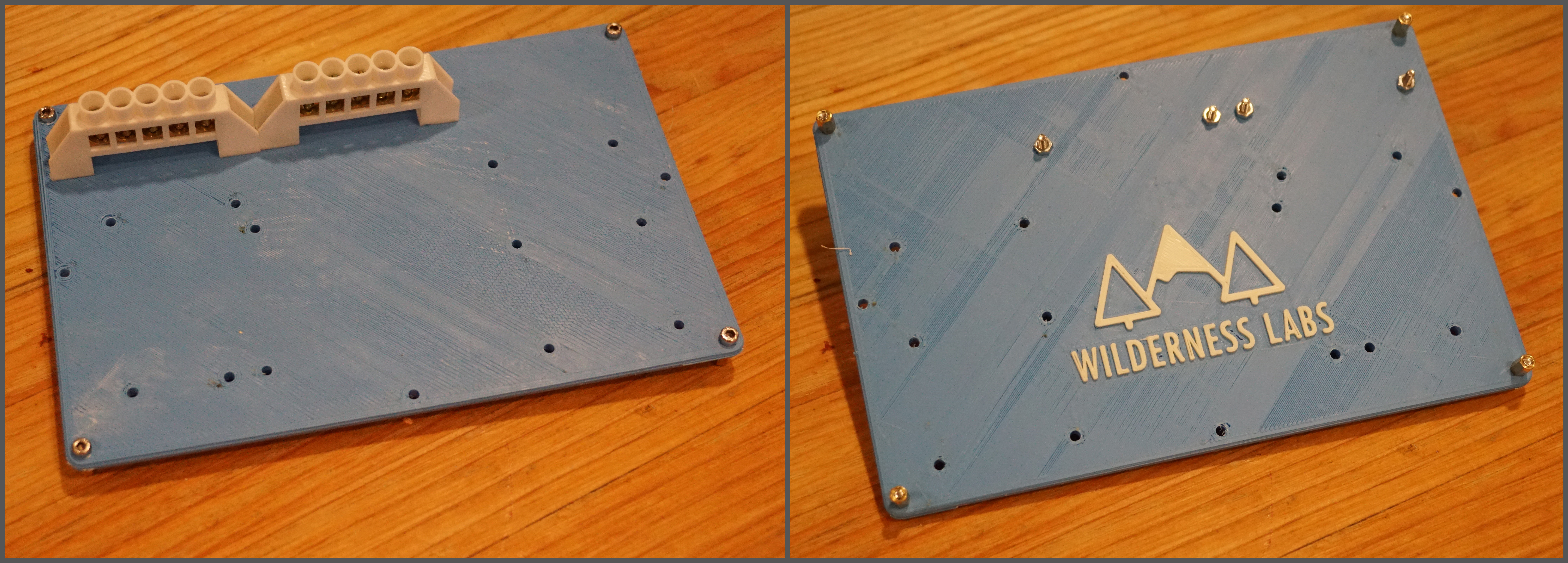
Once the holes have been cleaned, it’s time to start assembling the baseboard. First, using (4) 12mm M3 socket screws and (4) hex spacers, install “feet” on the corners of the board. This gives clearance on the board by raising it off the work surface. Then attach the terminal blocks as shown:
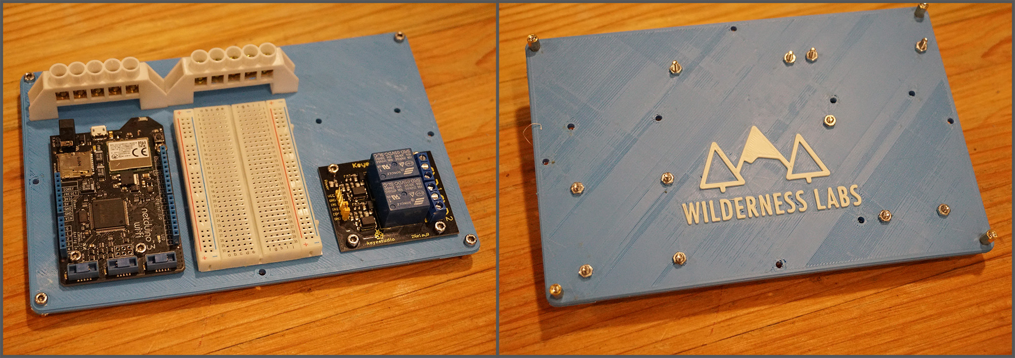
Next, attach the Netduino, half-size breadboard (it should have mounting tape on the back), and the relay using the 12mm M3 socket screws and hex nuts as shown below:
Once the boards and terminal blocks are on, put some mounting tape on the power adapter, and remove backing. Make sure to put it on the correct side:

Then attach the power adapter to baseboard. Make sure the USB cable fits as follows:

Step 3 – Wire the Power Adapter In
Next we want to wire the power adapter into our screw terminals. These screw terminals will be used to distribute our household electrical power (120V/240V). However, I’ve found that these screw terminals are meant to handle a little larger wire, so I recommend stripping and then soldering the end of the wire so it provides a more solid contact point:
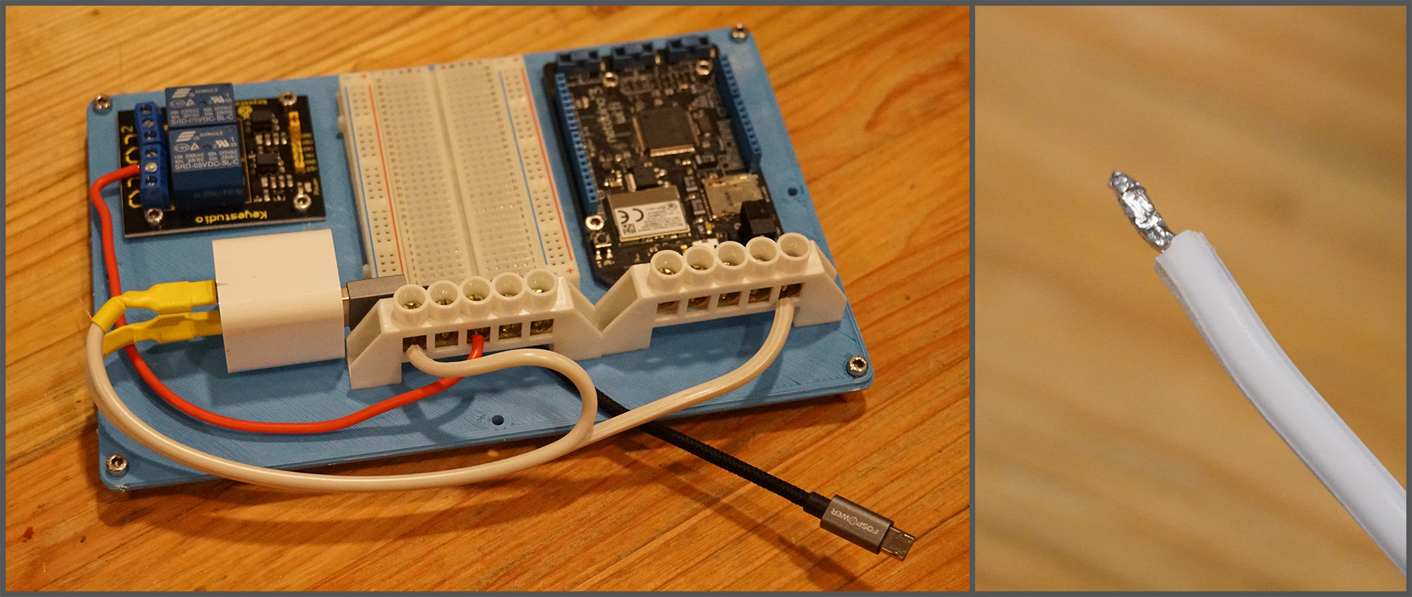
It does’t matter which wire goes to which screw terminal, as long as the wires are divided between the blocks. You can ignore the red wire above for now.
Step 4 – Add the DC Circuit Control Wires
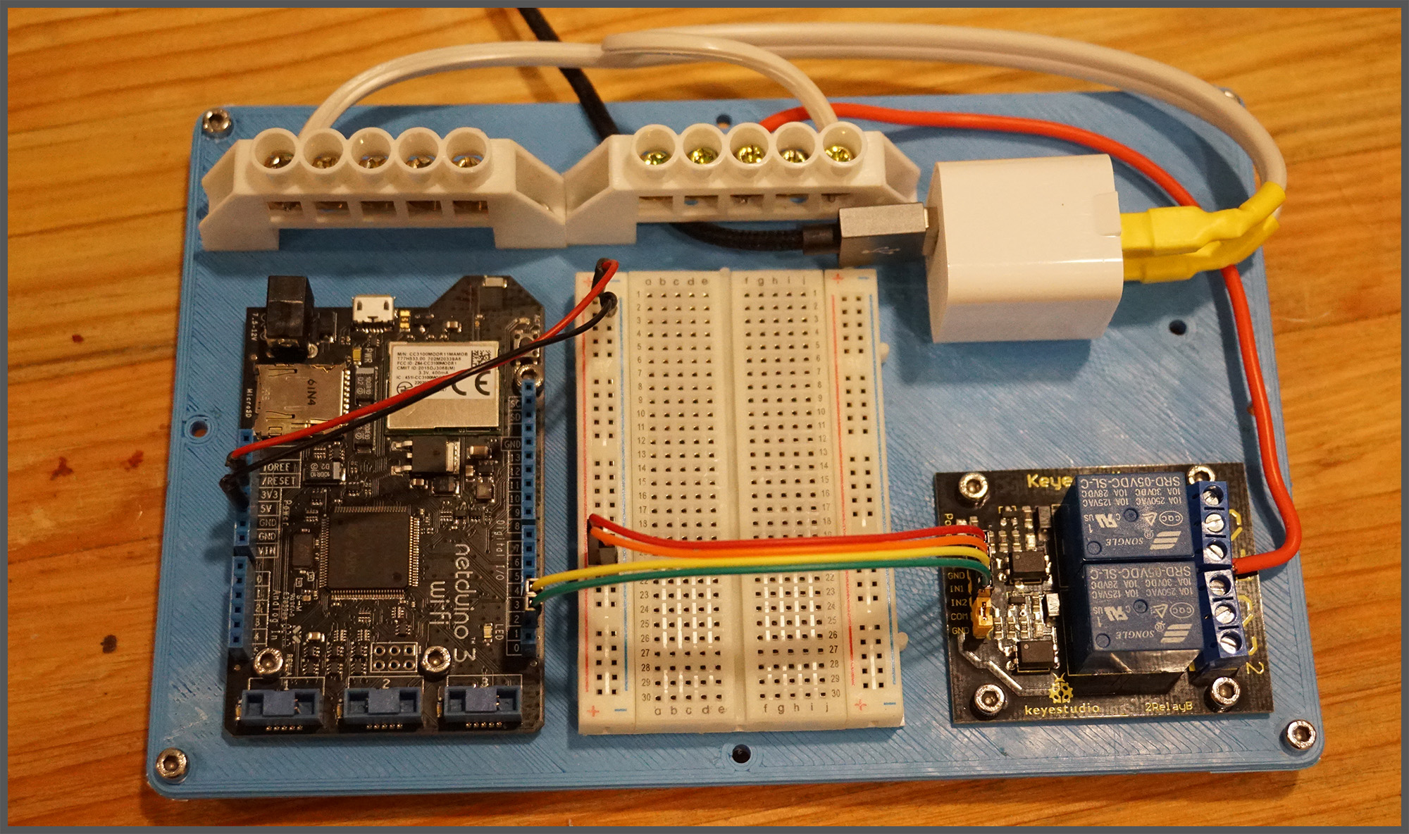
Now we can add all the DC control circuit wires. The wiring for this is very simple; the relay requires power and ground and then a digital IO wire for each relay.
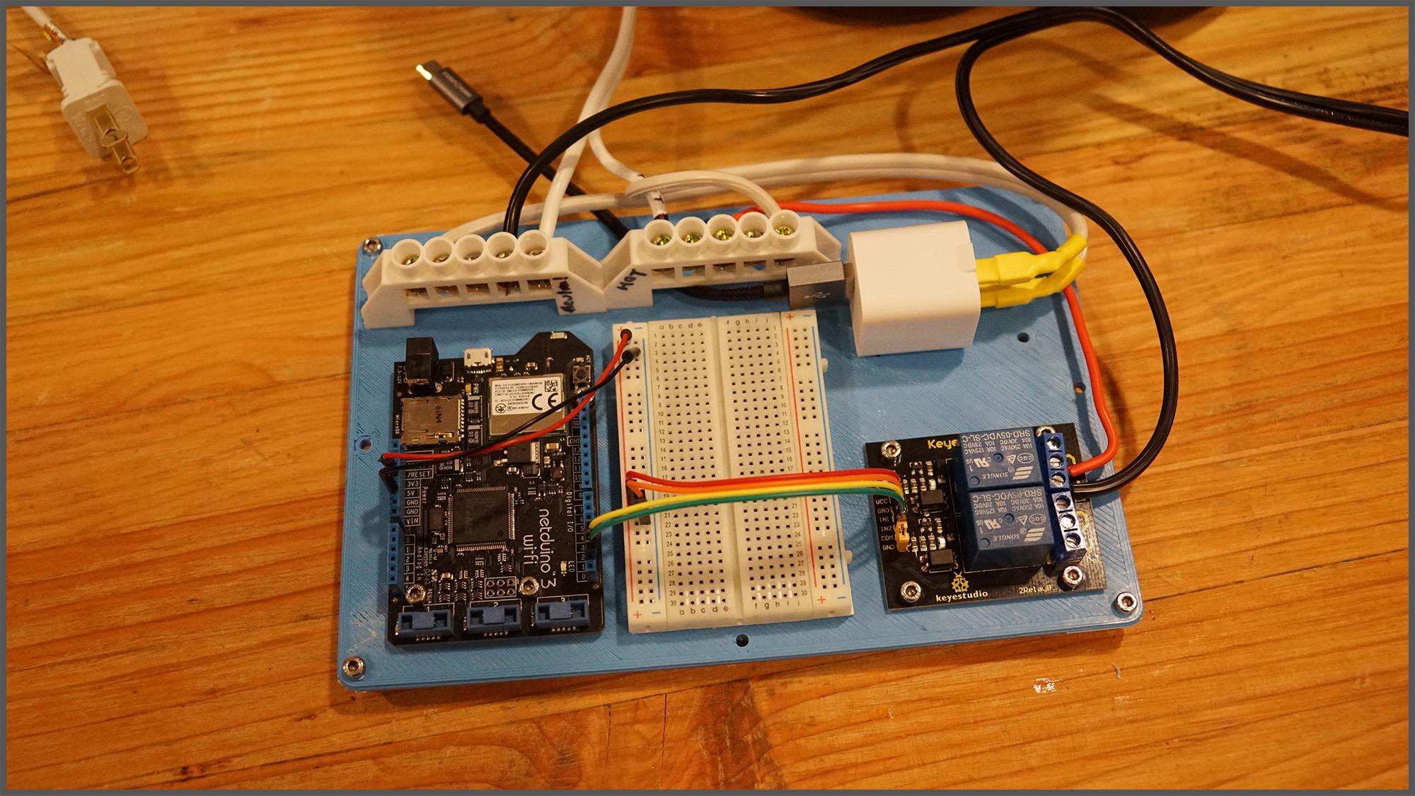
In this example, the breadboard is not actually needed, but by having it, we can add more complex circuits later. In the photo below, you can see that I’ve used male to male jumpers to wire the power rail (3.3V and GND) of the Netduino to the left power rail on the breadboard. This gives us a common power rail to add more circuits. I’ve also tied that into the relay with the red and orange wires. Note that it really doesn’t matter what colors of wire you use.
Finally, I’ve wired the Netduino digital IO pins 2 and 3 to the IN2 and IN1, respectively, on the relay board. In our case, we’ll actually only use one of the two relay channels available. Note that for the relay board, you’ll need male to female jumpers, since the relay exposes male pins.
Step 5 – Prepare the Appliance Cord
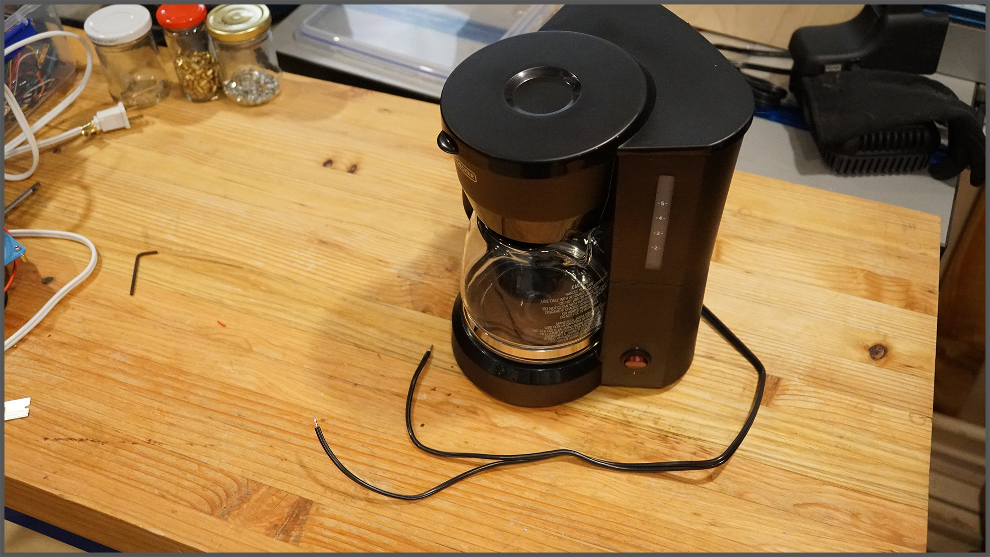
Next, we need to cut the plug off of the coffee maker, strip the ends, and optionally, add a little solder:
Step 6 – Add our Household Electrical Power
Next, cut and strip the end of the extension cord. It’s a good idea to mark the Hot and Neutral sides, though in practice, with AC appliances, it almost never matters. For North American plugs the hot side is the smaller prong, and the Neutral side is the larger prong. For other plugs, refer to this Wikipedia article.

Then, connect the household power extension cord to the terminal blocks. Each terminal block should get one of the wires. I’ve labeled the neutral and hot, but again, it’s unnecessary 99.9% of the time: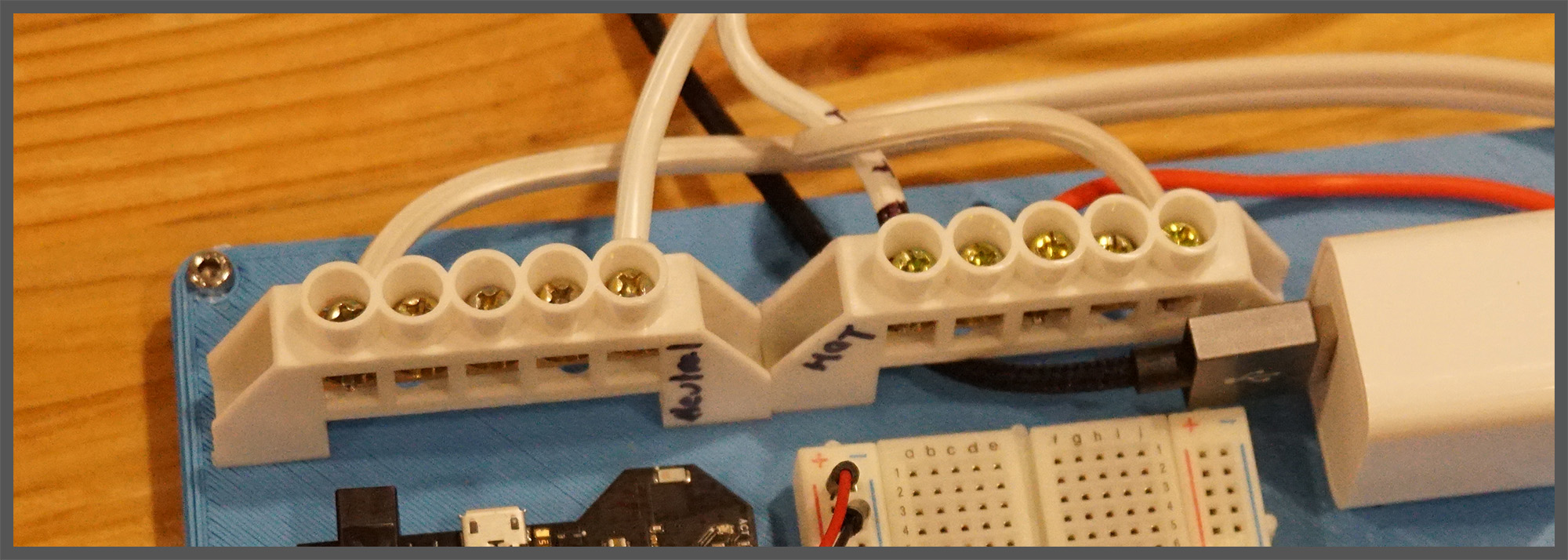
Step 7 – Wire the Coffee Pot into the Circuit
The last thing we need to do to finish our circuit is to wire the coffee pot into the relay. A relay is an electromechanical switch that uses an electromagnet to physical move the switch. Relays are often used in setups like this because you can control larger and/or different types of current with a small DC current. In this case, we’re using 3.3V of DC to control a switch that controls 120V or 240V AC. For a more detailed discussion of how they work, see our relay guide.
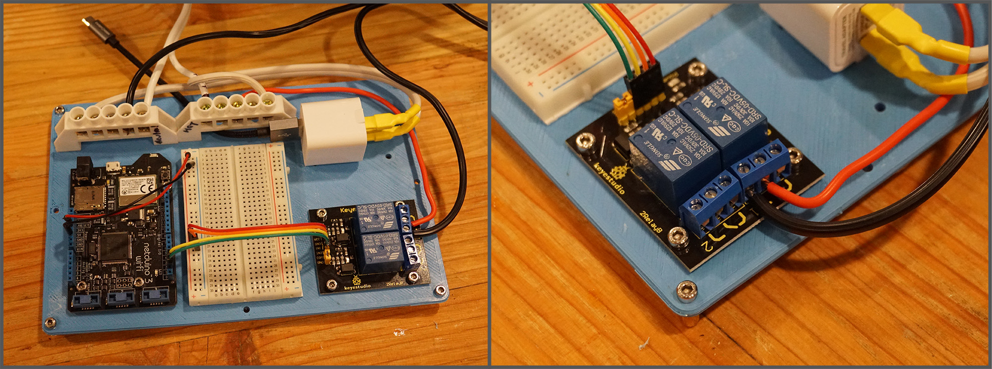
The relay board that we’re using is a two channel relay board, meaning that it has two relays, to control two separate circuits. We’re only going to need one relay for now. For each relay, there are three screw terminals that correspond to the normally closed wire, the power wire, and the normally open wire. Normally closed and normally open refer to whether or not that side of the switch is connected to the center power wire when the relay is not powered. In this case, we need to connect the center terminal to the hot side of our household electrical terminal block, and then the normally open terminal to one of side of the coffee maker cord. The other wire of the coffee maker should then go to the neutral main screw terminal block.
The idea here is that when the relay is powered, it switches to connect the normally closed side to the power. This then creates a closed circuit through the coffee maker of neutral household main > coffee maker > normally closed terminal > hot household main:
When all the wiring is done, it should look something like the following:
Step 8 – Double-Check the Wiring
Now that everything is wired up, it’s time to test our AC circuit to make sure that we don’t cause a short-circuit. While it’s unplugged from the wall, double-check that the extension cord wires are firmly in place with good connection and that they’re on different terminal blocks. Putting them on the same terminal block will cause a short-circuit and immediately cause the circuit breaker (or fuse) that your wall outlet is connected to, to trip. It may also cause sparks. we don’t want that.
Next, make sure that the coffee pot wires are also on different terminal blocks; one should be on neutral, and the other should connect to the hot terminal block, by way of the relay.
Finally, make sure that the USB adapter wires also go to different terminal blocks; one to the neutral and one to the hot.
After you’ve double-checked all those connections, plug the USB cable into the Netduino, and plug the extension cord into the wall outlet. If all is well, the Netduino and relay board should be powered. Unplug the extension cord from the wall, an unplug the USB cable from the Netduino. Next, we’re going to program the Netduino.
Step 9 – Test Control from Code
Plug the Netduino into your computer, launch Visual Studio, create a new .NET MicroFramework application called Connected_Coffee_SimpleControl, and add references to the following dlls:
- Microsoft.SPOT.Hardware
- System
- SecretLabs.NETMF.Hardware.Netduino
Next, paste the following code in your program.cs file:
 using Microsoft.SPOT.Hardware;
 using SecretLabs.NETMF.Hardware.Netduino;
 using System.Threading;

 namespace Connected_Coffee_SimpleControl
 {
     public class Program
     {
         public static void Main()
         {
             // create an output port (a port that can be written to) and
            // connect it to Digital Pin 2
             OutputPort relay = new OutputPort(Pins.GPIO_PIN_D2, false);

             // run forever
             while (true)
             {
                 relay.Write(true); // turn on the relay
                 Thread.Sleep(5000); // Leave on for 5 seconds
                 relay.Write(false); // turn off the relay
                 Thread.Sleep(5000); // leave off for 5 seconds
             }
         }
     }
 }
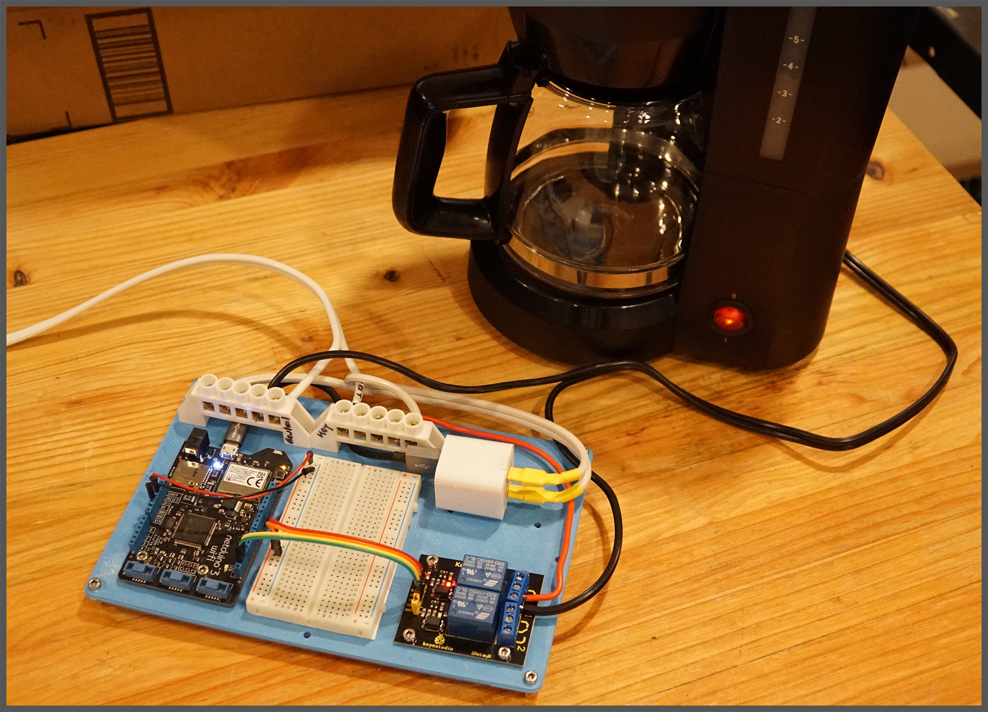
This code will simply turn the coffee pot on for 5 seconds, then turn it off, and repeat. To test it, make sure the switch on the coffee pot is on, then plug the extension cord for the appliance control board into the wall and deploy the app. You should hear an audible “click” as the relay actuates, and the coffee maker light should come on. It’ll stay on for five seconds, and then turn off.
And once the program is deployed, it will run as long as the Netduino is plugged into power. So after deploying the program, you can plug the Netduino back into the USB power adapter, plug the extension cord back into the wall, and see it run:
Step 10 – Pat yourself on the back!
Congratulations!! You’ve now built a basic control circuit for a connected appliance! In the next article in this blog series, we’re going to add the “connected” part of this project by adding a web API that runs on the Netduino so that we can control this remotely, from a web browser, or a mobile app!


